
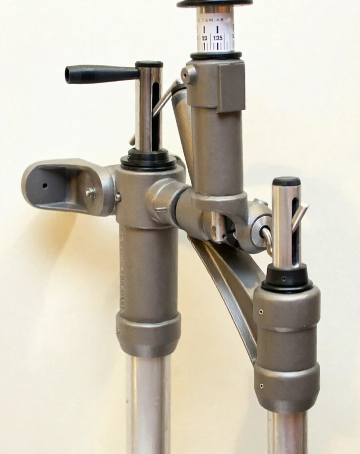
1. System Design & Compatibility

Comparative analysis of auxiliary rudder systems for offshore sailing

What size vessel is the S 600 designed for?

It is designed for large-displacement sailboats, specifically those with a Length Over All (LOA) between 36 and 60 feet (11 to 18 meters).

What type of self-steering system does it use?

The S 600 is an Auxiliary Rudder system. Unlike pure servo-pendulum models, it features its own independent rudder blade that works in tandem with a perfectly synchronized sensing pendulum.

Can it function as an emergency rudder?

Yes. The S 600 is a dual-function system: it operates as a windvane self-steering gear and as a "Ready-To-Go" emergency rudder in the event of a catastrophic failure of the vessel's main rudder.

Is it suitable for boats with hydraulic steering or a center cockpit?

Yes, it is the technically correct choice for these configurations. Being an independent auxiliary rudder system, it does not rely on the mechanical linkages or lines of the vessel's primary steering gear.

Does it require routing steering lines or blocks through the cockpit?

No. One of its main technical advantages is that it eliminates the need for steering lines across the cockpit, keeping the area clear and free of obstructions.
2. Performance & Operation

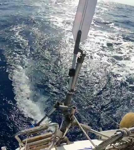
Illustration of boat heeling affecting off-center rudder submersion

How does it perform in light wind conditions?

The S 600 is significantly more sensitive than standard servo-pendulum systems in light airs and faint breezes.

How much steering power does it deliver?

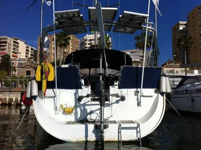
It is the strongest and most powerful model in the entire South Atlantic product range. Due to its position at the absolute aft end of the transom, it optimizes the turning lever arm and can deflect its rudder blade up to 35 degrees to maintain course.

How does it manage the vessel's weather helm?

It allows the ship's main rudder to be locked in a fixed position to counteract and balance out weather helm, leaving the S 600 to handle all subsequent fine tracking and course corrections.

Does it require electrical power to operate?

No. Like all South Atlantic systems, the S 600 is entirely mechanical and operates with net-zero electrical consumption.

3. Setup & Adaptability

Close up of an auxiliary rudder blade submersion in water

Is it difficult to install?

No, it is designed for straightforward DIY (Do-It-Yourself) owner installation. The estimated mounting time—from unboxing to sea trials—is only 2 to 4 hours.

Can the unit be customized?

Yes, the S 600 can be custom-tailored to meet the specific transom design and architectural requirements of your sailboat.

4. General Overview & Models (S 600 I and II)

The rudder blade of a South Atlantic S 600 system has unique characteristics, as it is not a passive blade but rather a pendulum servo-assisted blade. The system features a dual function: it not only serves as a windvane for self-steering course control, but it is also sized to natively act as a fully operational emergency rudder.

There are important differences depending on the model and its evolution:

  • S 500 / S 600 Models: They use the full-size auxiliary rudder blade (0.27 m² / 0.36 m²) because they are autonomous systems that do not transfer lines to the original wheel or tiller. The main face surface (the blade profile) is 0.36 m².
  • S 600 I Blade: It features a surface area of 0.30 m² (3 square feet), with measurements of 30 cm wide by 100 cm high.
  • S 600 GII (or II) Blade: It features an exact area of approximately 3.9 sq ft (0.36 m² or 3.66 square feet), with typical dimensions of 120 cm high by 33 cm wide (approximate thickness of 60 mm).

5. Operating Dynamics & Servo-Assistance

  • "Dual Rudder" Principle (Servo-Auxiliary): Unlike pure auxiliary rudders (such as the Hydrovane or the HF 450), where the wind vane moves the blade directly with wind force, in the South Atlantic S 600 the wind vane moves a servo-pendulum. The wind vane does not push the auxiliary blade directly; instead, it only actuates a small submerged pendulum fin.
  • Servo-pendulum mechanism: As it pivots with the boat's speed, this fin generates a massive hydraulic force that displaces the pendulum to the sides. This mechanical movement assists and rotates the auxiliary rudder blade.
  • Force multiplication: By coupling a servo-pendulum fin that uses the boat's own speed to pivot the blade, a massive turning power is achieved. This completely eliminates the need for transmission lines to the boat's main wheel or tiller. Furthermore, this servo-assistance allows the use of a very thin and efficient profile that drastically reduces drag. Thanks to this turning power, a small rudder can effortlessly steer vessels up to 60 feet in length or 27 tons of displacement.

7. Certified Emergency / Spare Rudder Capability

  • Main rudder locking: During sailing with the S 600, the boat's main rudder remains locked amidships (or slightly trimmed to compensate for weather helm).
  • Oversized structural strength: Since the main rudder remains locked in the center while the S 600 operates, all the structural load falls on the auxiliary blade. For this reason, its construction is solidly oversized to fulfill the certified function of an emergency rudder, 100% operational in the event of a catastrophic failure of the sailboat's original rudder.

8. Materials, Structure & Construction

  • High-strength shaft: The blade is bolted and rigidly coupled to a solid vertical shaft or high-strength Duplex stainless steel connector.
  • Cast body: The upper bracket and the main structure supports use marine aluminum.
  • Modern profile: In current models, the blade features an optimized hydrodynamic section that generates maximum lift with minimum wetted surface.
  • Quick-release system: Its modular design allows the blade and its vertical shaft to be removed independently from the main structure using aluminum release clamps. This greatly facilitates storage, transport, or maintenance tasks when the boat is in port, as well as protecting the blade from marine life when not in use.
  • Grease-free bearings: It uses technical material friction bushings (POM) that work exclusively with seawater. They must never be greased, as grease would trap salt and completely block the system's rotation.
WARNING: POM bearings work exclusively with seawater as a lubricant. The use of grease will cause total system lock-up.

9. Bearing Materials Comparison: POM vs. PTFE (Teflon)

When evaluating which engineering plastic best resists compression and maintains dimensional stability for shaft bearings:

  • POM (Polyacetal / Delrin): Wins by a huge margin in compression strength and dimensional stability. It is an extremely rigid, hard plastic with high mechanical strength that withstands very high static and dynamic loads without deforming or creeping (its compression strength is approximately 80 to 100 MPa). It maintains its shape and does not easily crush under constant pressure.
  • PTFE (Pure Teflon): It is a soft, flexible material with a tendency to cold flow (creep). Under a constant compressive load or a strong impact, it tends to "flow" or crush over time, losing its original shape due to its very low compression strength, of only 5 to 10 MPa.

Mechanical Comparison Table for the Rudder Shaft

Property POM (Polyacetal / Delrin) PTFE (Pure Teflon)
Compression Strength Very High (Rigid, does not crush) Very Low (Deforms and flows under load)
Friction Coefficient Low (Good sliding) Extremely Low (The slipperiest)
Moisture Absorption Practically null (~0.2%) Null (0%)
"Self-lubricating" Behavior Good (Low friction coefficient for a hard plastic) Excellent (Its greatest virtue)

10. Technical Analysis of the Auxiliary Rudder Shaft: Tube vs. Solid

The tubular shaft design of the S 600 auxiliary rudder presents critical mechanical differences depending on whether a tubular or solid structure is used:

  1. 40 mm Tube (5 mm Wall) in Duplex: This is the option used by the S 600 on the blade and is clearly superior in this assembly. It flexes half as much and withstands 40% more load before structurally deforming. Its hollow design optimally leverages the laws of physics to resist bending moments with the least possible weight.
  2. 30 mm Solid Shaft in Duplex: Although it is extremely resistant to absolute breakage due to the nobility of the material, being thinner it will suffer from a lack of rigidity. This will translate into a mechanically more elastic ("rubbery") rudder, with a greater tendency to vibrate or misalign under intense hydrodynamic loads.

Section Modulus Formula for a Circular Tube and Allowable Load

F = 1000 mm × 450 MPa × 4,295 mm³ ≈ 1,933 N ≈ 197 kgf

Mechanical Performance Comparison Table

Shaft Configuration Section Modulus W (mm³) Allowable Force F (N) Allowable Force F (kgf)
Solid Shaft (30 mm) 2,650.7 1,193 ≈ 121
Tubular Shaft (40/5 mm Tube) 4,295 1,933 ≈ 197

Technical conclusion: The 40/5 mm tubular design offers 62% more bending resistance than the 30 mm solid shaft; the geometry of the profile is just as important as the material used.

11. Technical Resources & Guides

Explore our complete technical library in the FAQ and Technical Reports sections. Our technical documentation covers:

Contact Details

Phone: +54 911 2158 2504
E-mail:
Website: www.south-atlantic.net

South Atlantic
Santiago del Estero 2175
CABA
Argentina

Design & Management

South Atlantic
Weko Park, Werther 33824
NRW, Germany

E-mail:

Newsletter Subscription

Subscribe to our newsletter to receive
the latest news and updates